

Simulation of temperature field in directional solidification casting of Nb–Si based alloys
-
摘要: 以鈮硅基高溫合金定向凝固鑄造過程為對象,通過實驗測試和反求法確定了鈮硅基高溫合金和型殼的熱物性參數,以及凝固過程各界面換熱系數等邊界條件;利用ProCAST軟件對不同抽拉速率下鈮硅基高溫合金凝固過程溫度場進行了模擬。結果表明,隨著抽拉速率由5 mm·min?1增加到10 mm·min?1,固/液界面離液態金屬錫表面的距離由12.1 mm下降到8.2 mm;平均糊狀區寬度逐漸變窄,由11.5 mm減小到10.4 mm。針對抽拉速率為5 mm·min?1的實驗結果表明,數值模擬結果與實際定向凝固實驗獲得的一次枝晶間距差異在6%以內,從一個方面驗證了溫度場模擬結果的正確性,相關結果可為鈮硅基高溫合金葉片定向凝固鑄造參數的確定提供參考。Abstract: With the increasing demand for improvements in the temperature capability of aero-engines, there is an urgent need to develop new-generation turbine blade materials. Compared with Ni-based superalloys that have a lower melting point (~1300 ℃), the higher melting point (>1750 ℃), lower mass density (6.6–7.2 g·cm–3), and high-temperature strength of the Nb–Si based alloys make them one of the most promising of the new-generation high-temperature structural materials. A directional solidification process can further enhance the performance of Nb–Si based alloys and lay a foundation for replacing the Ni-based single-crystal superalloys in service at higher temperatures. Accurately determining the thermal property parameters of Nb–Si based alloys and their interfacial heat transfer behavior during solidification is the key to their numerical simulation, which could accelerate the development of Nb–Si based alloys. As yet, however, there has been no research reported in relation to this issue. In this study, we used the directional solidification process of Nb–Si based alloys as the research object and the experimental testing and reverse methods to determine the thermal properties of Nb–Si based alloys and their shells as well as the boundary conditions of the heat transfer coefficient at the interface during the solidification process. To simulate the temperature field of the solidification process of Nb–Si based alloys at different drawing rates, we used ProCAST software. The results reveal that as the withdrawal rate increased from 5 to 10 mm·min?1, the distance between the solid/liquid interface and the surface of the liquid metal tin decreased from 12.1 to 8.2 mm, and the average width of the mushy zone gradually narrowed from 11.5 mm to 10.4 mm. The discrepancy in the spacing of the primary dendrites between the numerical simulation and the actual experimental results at a withdrawal rate of 5 mm·min?1 was within 6%, which verifies the correctness of the temperature-field simulation results. These results provide reference for the determination of the directional solidification casting parameters of turbine blades made of Nb–Si based alloys.
-
Key words:
- ProCAST /
- numerical simulation /
- directional solidification /
- liquid metal cooling /
- withdrawal rate
-
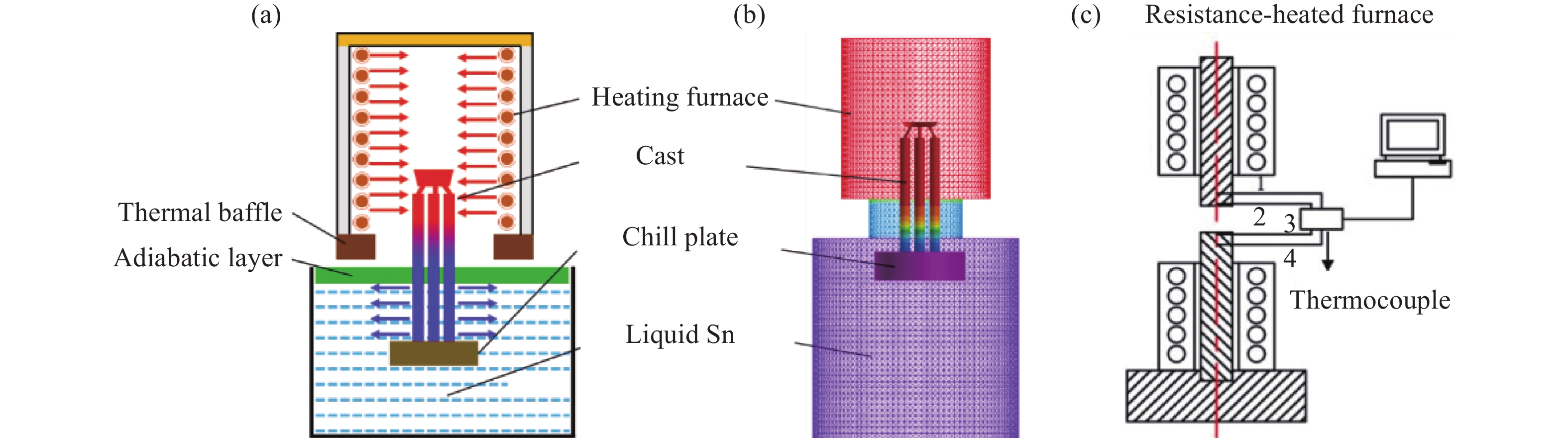
圖 1 鈮硅基高溫合金LMC定向凝固工藝示意圖(a)與有限元模型(b)、界面換熱實驗裝置示意圖(c)
Figure 1. Schematic (a) and finite element model (b) of LMC directional solidification process of Nb–Si based alloys; schematic of experimental heat transfer device at interface (c)
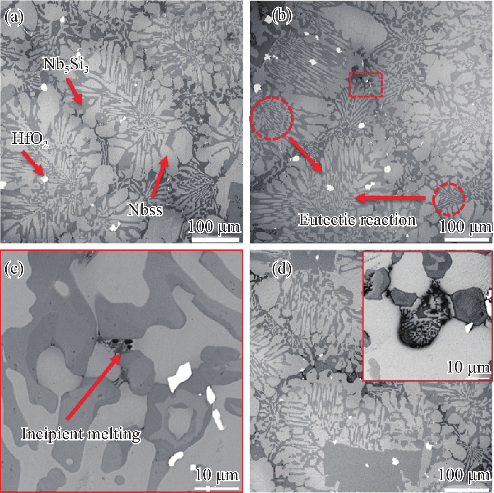
圖 2 不同溫度下等溫淬火實驗。(a)1580 ℃;(b)1600 ℃;(c)圖(b)中虛線方框處局部放大圖;(d)1620 ℃
Figure 2. Austempering experiments at different temperatures: (a) 1580 ℃; (b) 1600 ℃; (c) a partial enlarged view of the area enclosed by the dotted line in (b); (d) 1620 ℃
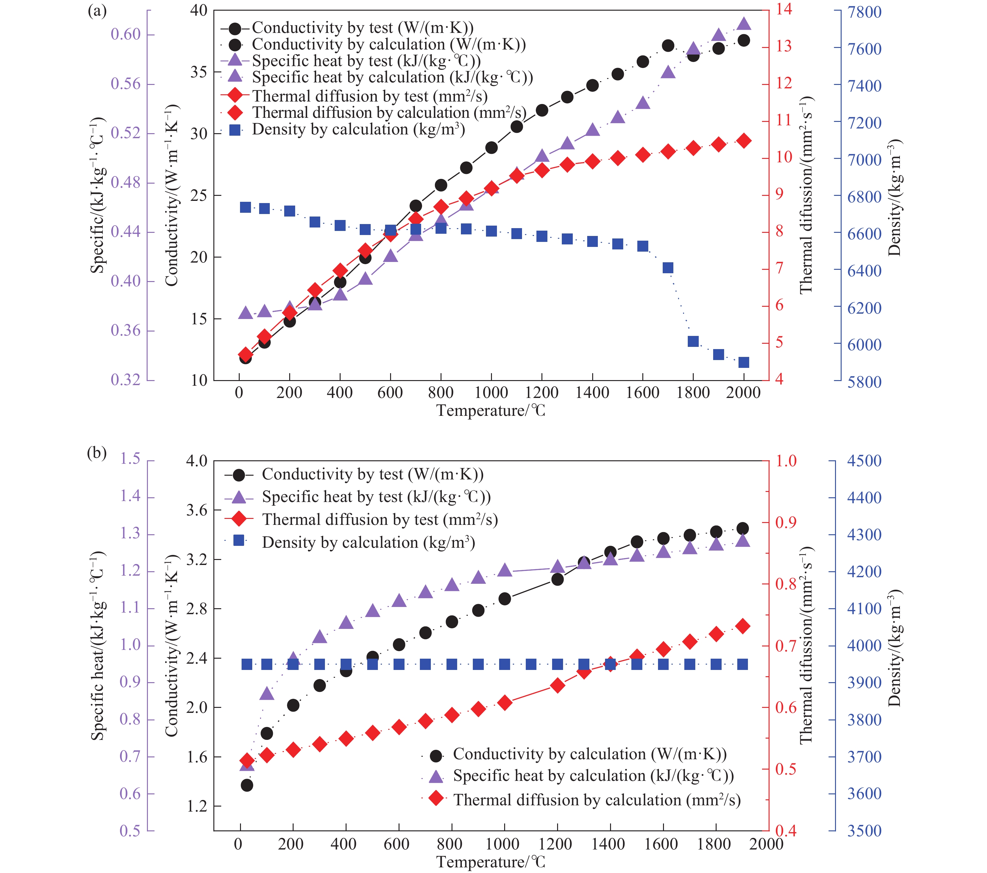
圖 3 鈮硅基高溫合金(a)和型殼(b)的熱物性參數
Figure 3. Thermophysical parameters of Nb–Si based alloys (a) and shell (b)
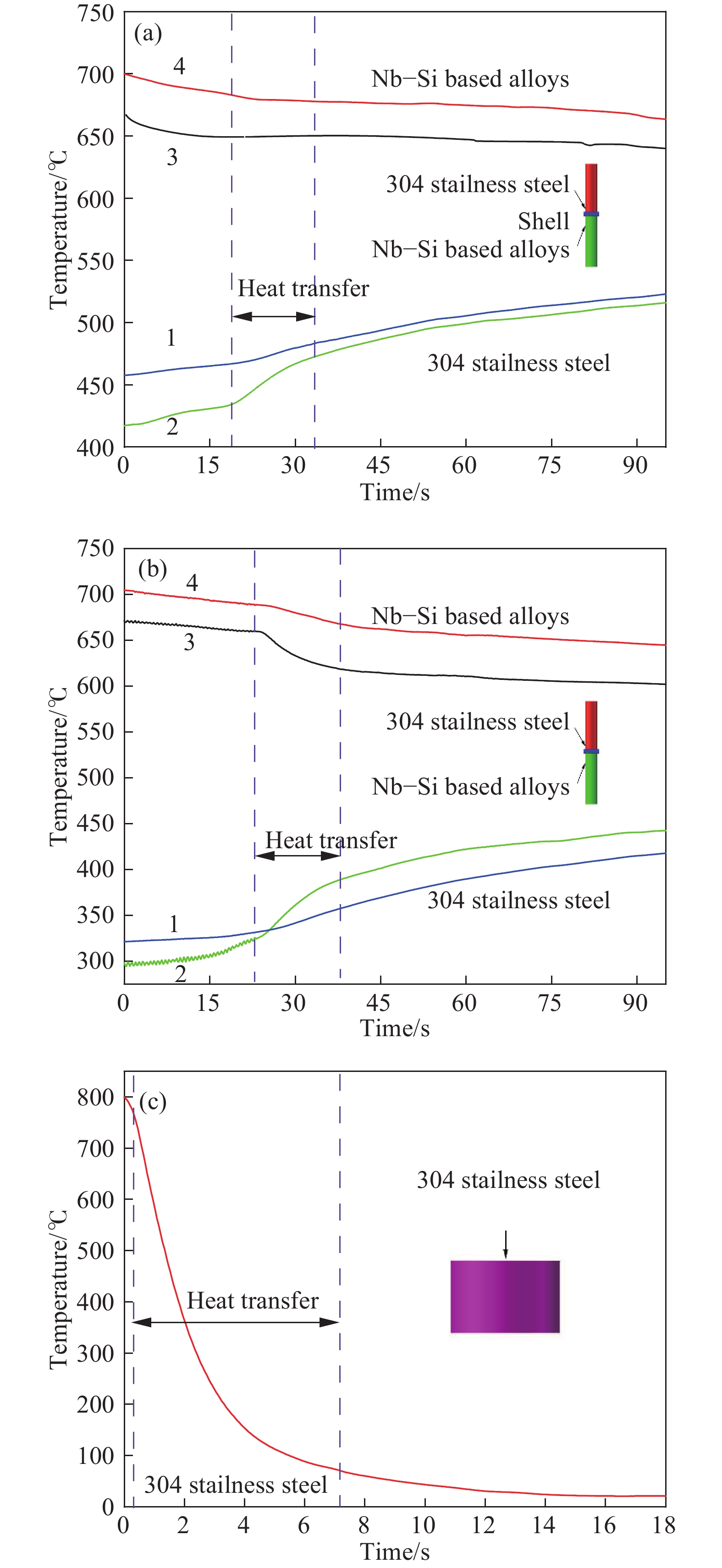
圖 4 界面換熱實驗實測溫度曲線變化。(a)304不銹鋼–型殼–鈮硅基高溫合金;(b)304不銹鋼–鈮硅基高溫合金;(c)304不銹鋼–水
Figure 4. Change in measured temperature curves of interface heat transfer experiment: (a) 304 stainless steel–shell–Nb–Si based alloys; (b) 304 stainless steel–Nb–Si based alloys; (c) 304 stainless steel–water
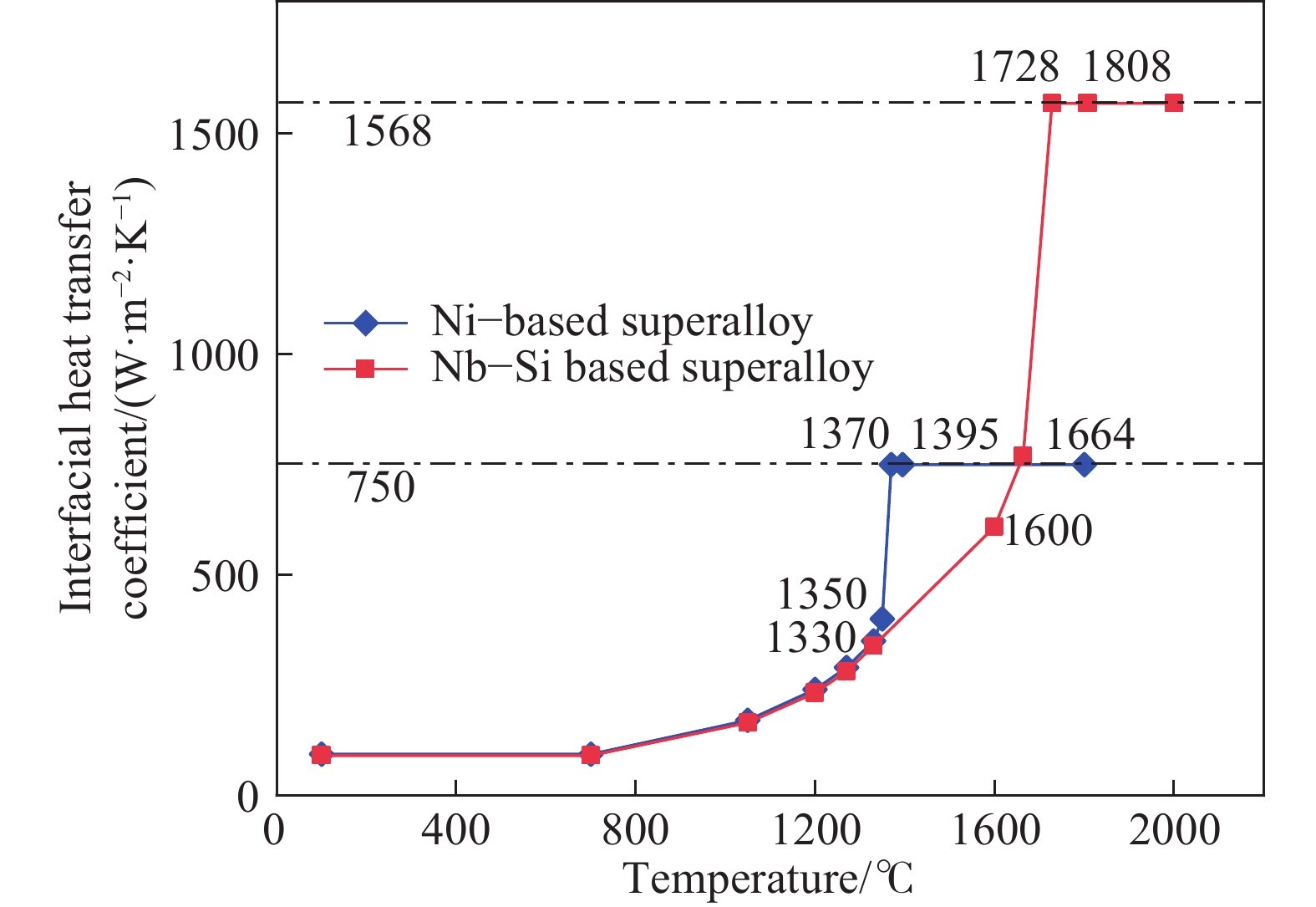
圖 5 合金與型殼的界面換熱系數
Figure 5. Interface heat transfer coefficients between alloy and shell
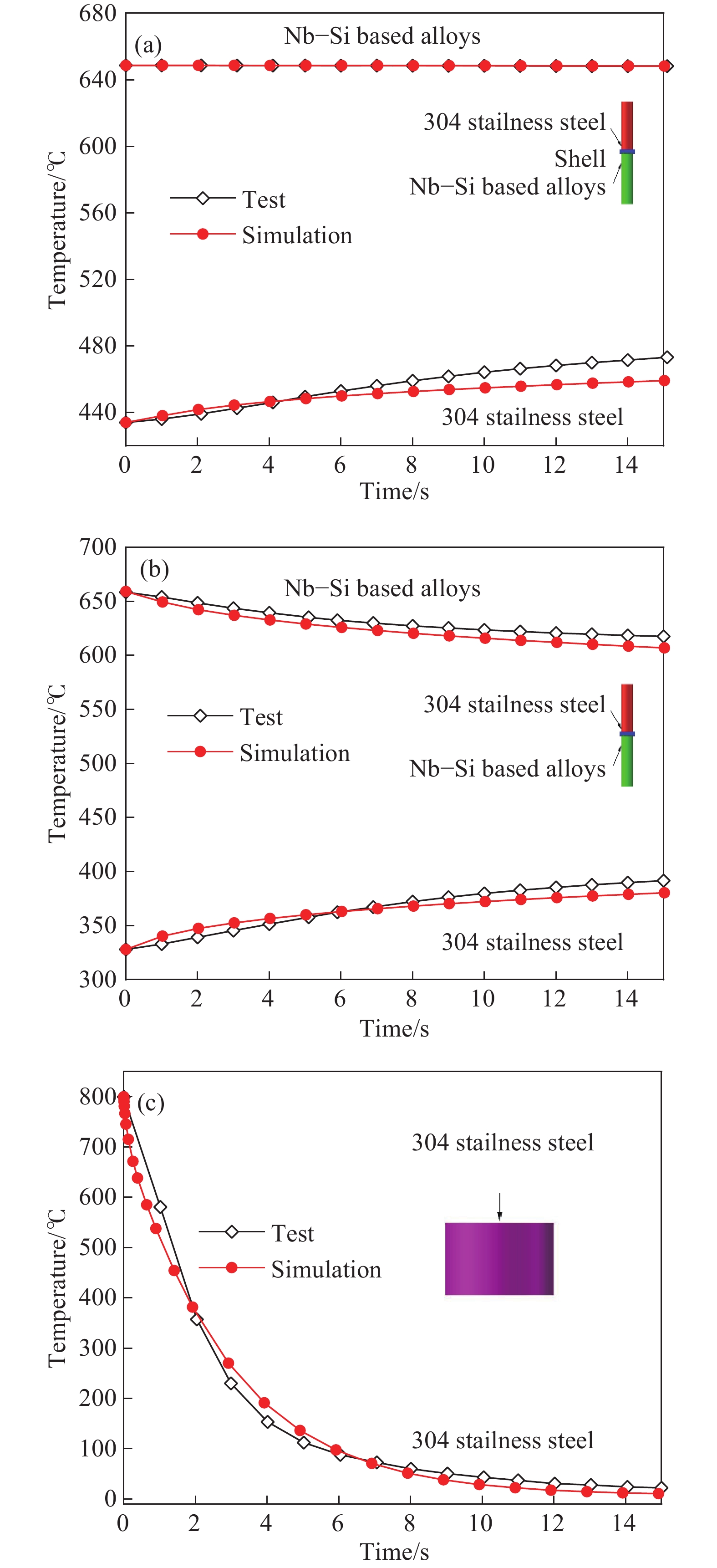
圖 6 界面換熱實驗實測溫度場與數值模擬溫度場對比。(a)304不銹鋼–型殼–鈮硅基高溫合金;(b)304不銹鋼–鈮硅基高溫合金;(c)304不銹鋼–水
Figure 6. Comparison of measured and numerically simulated temperature fields of interface heat transfer experiment: (a) 304 stainless steel–shell–Nb–Si based alloys; (b) 304 stainless steel–Nb–Si based alloys; (c) 304 stainless steel–water
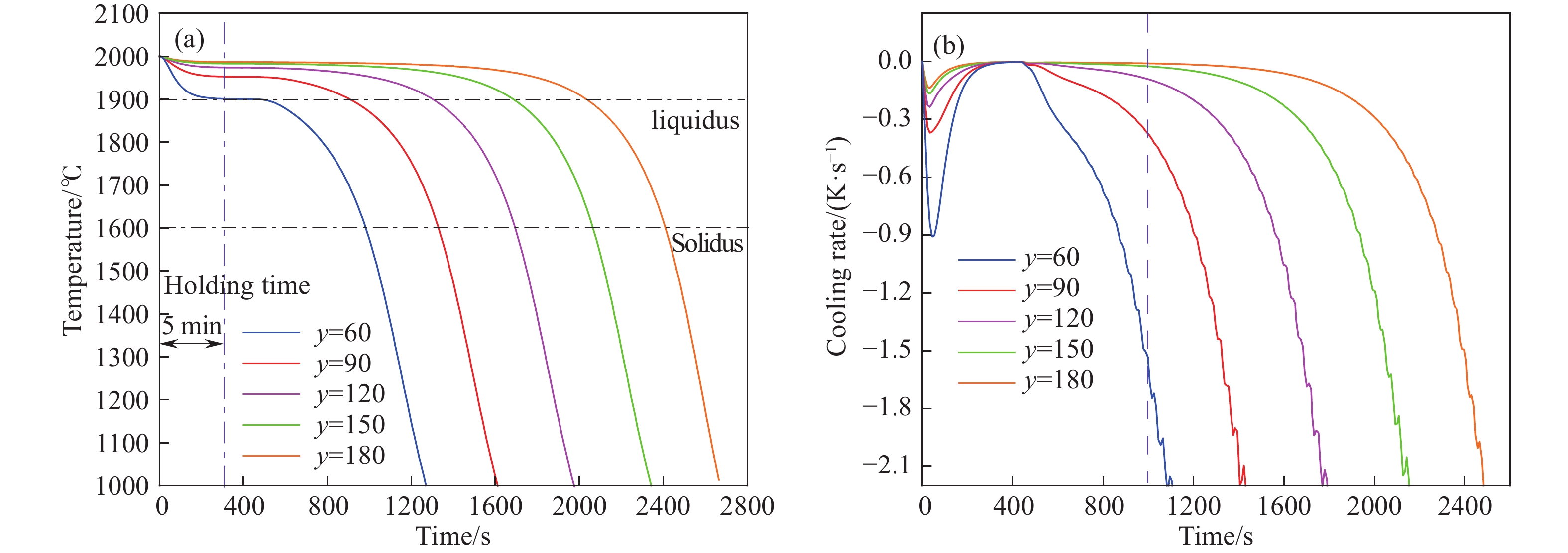
圖 7 抽拉速率為5 mm?min–1時的溫度場(a)和冷卻速率曲線(b)分布(鑄件底部為坐標原點)
Figure 7. Temperature field (a) and cooling rate curve (b) at a withdrawal rate of 5 mm?min–1 (the bottom of the casting is the origin of the coordinates)
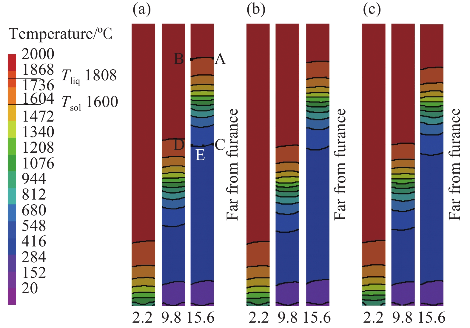
圖 8 不同抽拉速率下到達離激冷盤不同距離(2.2,9.8,15.6 cm)時的溫度場模擬結果。(a) 5 mm·min–1;(b) 8 mm?min–1;(c) 10 mm?min–1
Figure 8. Temperature field simulation results of castings at the different distance from the chilling disk (2.2 cm, 9.8 cm, 15.6 cm) with different withdrawal rates: (a) 5 mm·min–1; (b) 8 mm·min–1; (c) 10 mm·min–1
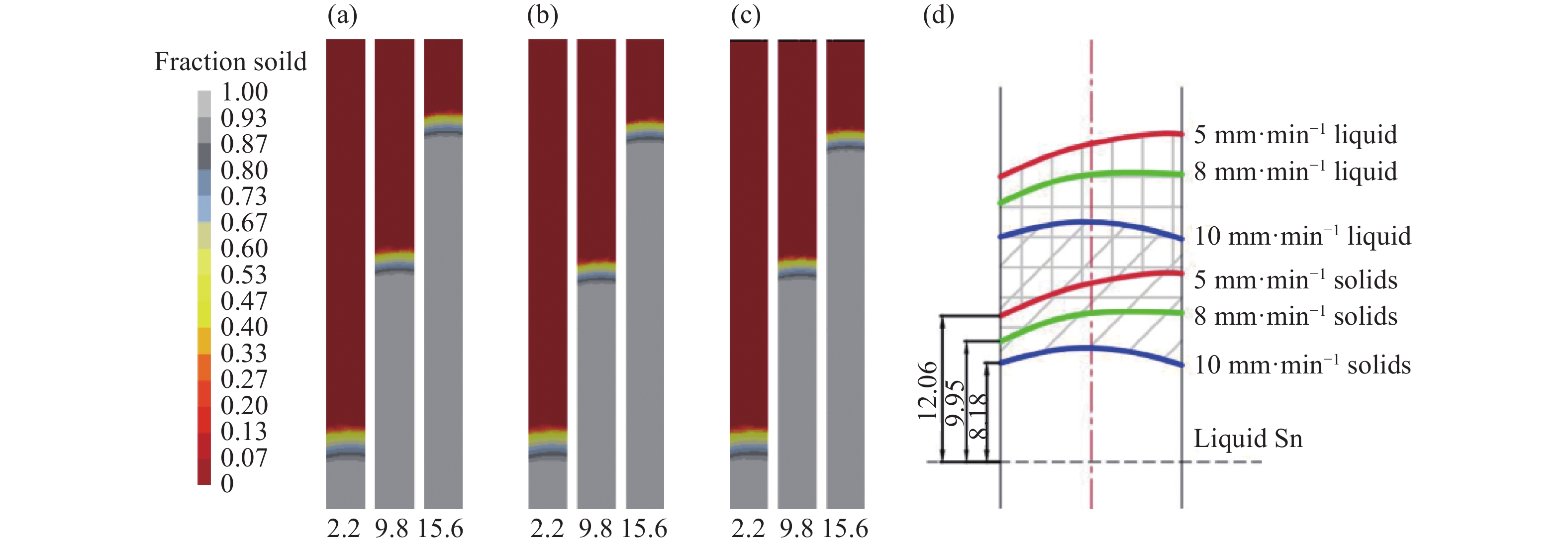
圖 9 不同抽拉速率下達到離激冷盤不同距離(2.2,9.8,15. 6 cm)時的固/液界面形狀模擬結果。(a)5 mm·min–1;(b)8 mm·min–1;(c)10 mm·min–1;(d)當鑄件距離激冷盤15.6 cm時,三種抽拉速率下固/液界面局部形狀放大圖,其中數字12.06、9.95和8.18 mm分別代表固/液界面離液態金屬錫表面距離
Figure 9. Simulation results for solid/liquid interface shape of castings at the different distances from the chilling disk (2.2 cm, 9.8 cm, 15.6 cm) with different withdrawal rates: (a) 5 mm·min–1; (b) 8 mm·min–1; (c) 10 mm·min–1; (d) enlargement of solid/liquid interface shapes when casting is 15.6 cm away from the chilling disk at three different withdrawal rates, and the figures 12.06, 9.95 and 8.18 mm represent the distance between the solid/liquid interface and the surface of the liquid tin, respectively
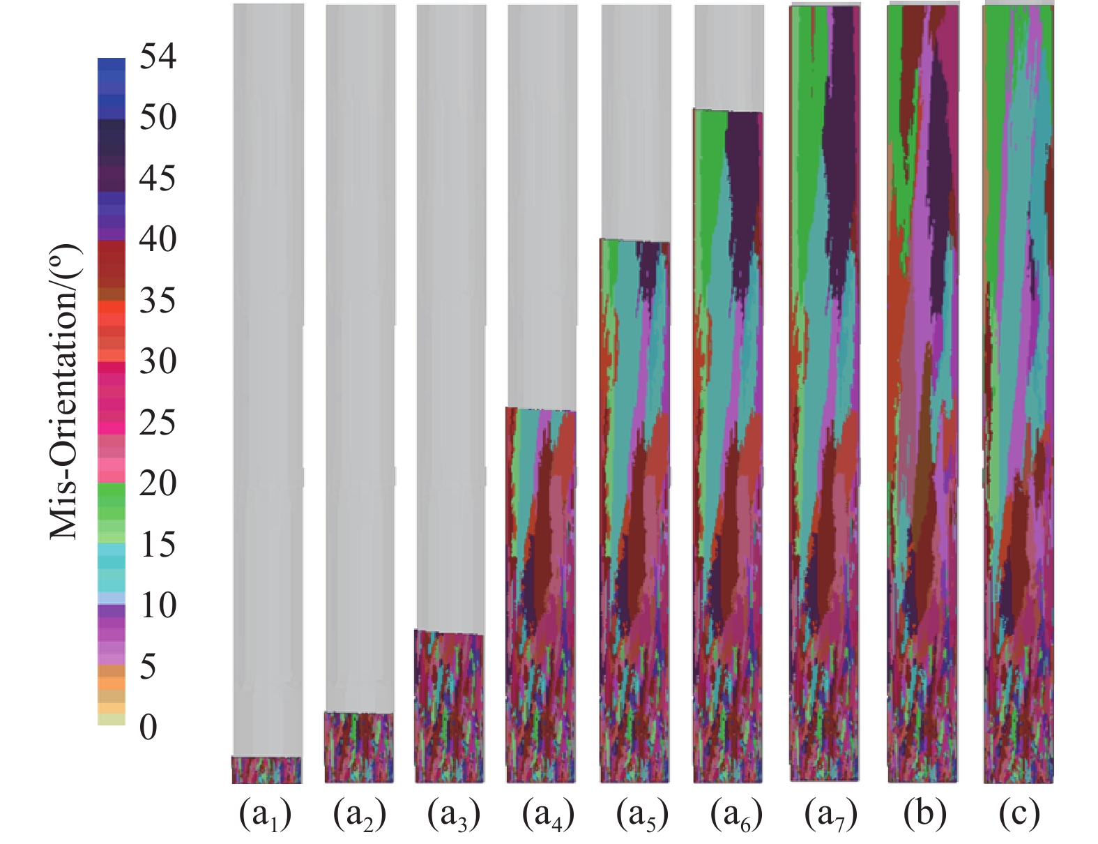
圖 10 不同抽拉速率下晶粒微觀組織模擬。(a1~a7)抽拉速度為5 mm?min–1,距離底端高度分別為5,18,38,98,138,178,200 mm;(b)抽拉速度為8 mm?min–1;(c)抽拉速度為10 mm?min–1
Figure 10. Simulation of grain microstructures at different withdrawal rates: (a1–a7) withdrawal rate of 5 mm?min–1, the heights from the bottom are 5, 18, 38, 98, 138, 178, and 200 mm, respectively; (b) withdrawal rate of 8 mm?min–1; (c) withdrawal rate of 10 mm?min–1
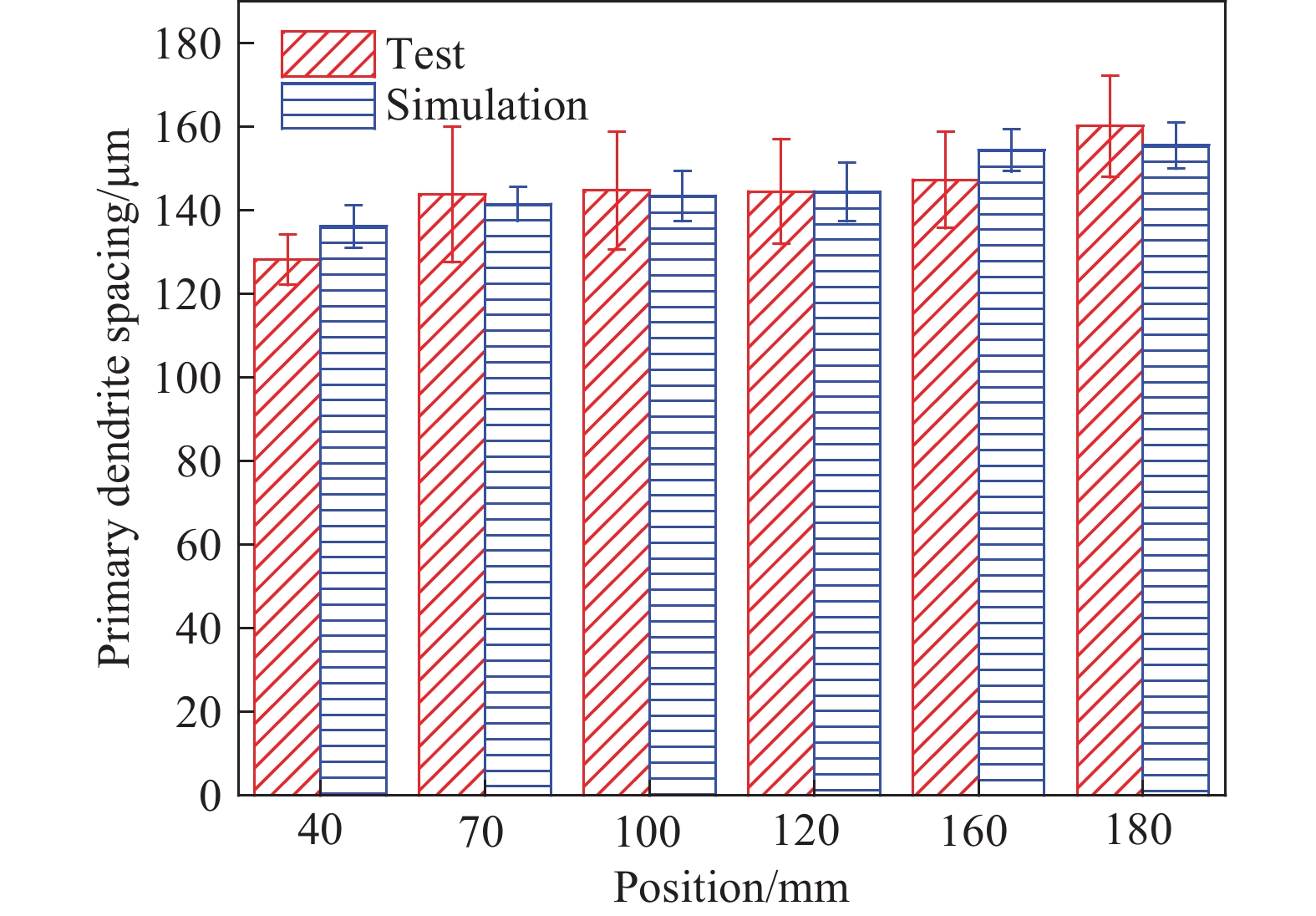
圖 11 距離鑄件底端不同高度的一次枝晶間距模擬與實驗結果對比
Figure 11. Comparison of spacing of primary dendrites between simulated and experimental results at different heights from the bottom of the casting
表 1 型殼表面的位置相關邊界條件的參數[19]
Table 1. Parameters of position-dependent boundary conditions of the shell surface[19]
Location Emissivity Interface heat transfer
coefficient / (W·m–2·K–1)Ambient temperatue / ℃ Above baffle 0.4 — 2000 Baffle — 500 425–2000 Below baffle — 4000 350  下載: 導出CSV
www.77susu.com
下載: 導出CSV
www.77susu.com<span id="fpn9h"><noframes id="fpn9h"><span id="fpn9h"></span> <span id="fpn9h"><noframes id="fpn9h"> <th id="fpn9h"></th> <strike id="fpn9h"><noframes id="fpn9h"><strike id="fpn9h"></strike> <th id="fpn9h"><noframes id="fpn9h"> <span id="fpn9h"><video id="fpn9h"></video></span> <ruby id="fpn9h"></ruby> <strike id="fpn9h"><noframes id="fpn9h"><span id="fpn9h"></span> -
參考文獻
[1] Ma X, Guo X P, Fu M S, et al. Direct atomic-scale visualization of growth and dissolution of γNb<sub>5</sub>Si<sub>3</sub> in an Nb–Ti–Si based alloy via in-situ transmission electron microscopy. <italic>Scripta Mater</italic>, 2019, 164: 86 doi: 10.1016/j.scriptamat.2019.01.040 [2] Zhang S S, Liu W, Sha J B. Microstructural evolution and mechanical properties of Nb–Si–Cr ternary alloys with a tri-phase Nb/Nb<sub>5</sub>Si<sub>3</sub>/Cr<sub>2</sub>Nb microstructure fabricated by spark plasma sintering. <italic>Prog Nat Sci Mater Int</italic>, 2018, 28(5): 626 doi: 10.1016/j.pnsc.2018.09.001 [3] Ma X, Guo X P, Fu M S. HRTEM observation of silicides and Laves phase precipitates in Nb–Ti–Si based alloys. <italic>Int J Refract Met Hard Mater</italic>, 2019, 78: 138 doi: 10.1016/j.ijrmhm.2018.09.005 [4] Wang N, Jia L N, Kong B, et al. Eutectic evolution of directionally solidified Nb–Si based ultrahigh temperature alloys. <italic>Int J Refract Met Hard Mater</italic>, 2018, 71: 273 doi: 10.1016/j.ijrmhm.2017.11.001 [5] Bolbut V, Bogomol I, Loboda P, et al. Microstructure and mechanical properties of a directionally solidified Mo–12Hf–24B alloy. <italic>J Alloys Compd</italic>, 2018, 735: 2324 doi: 10.1016/j.jallcom.2017.11.352 [6] Park K B, Choi J, Lee S Y, et al. Sintering behaviour of Nb–16Si–25Ti–8Hf–2Cr–2Al alloy powder fabricated by a hydrogenation–dehydrogenation method. <italic>Mater Sci Technol</italic>, 2020, 36(12): 1372 [7] Guo Y L, Jia L N, Kong B, et al. Heat treatment induced phase transition and microstructural evolution in electron beam surface melted Nb–Si based alloys. <italic>Appl Surf Sci</italic>, 2017, 423: 417 doi: 10.1016/j.apsusc.2017.05.248 [8] Majumdar S. A study on microstructure development and oxidation phenomenon of arc consolidated Mo–Nb–Si–(Y) alloys. <italic>Int J Refract Met Hard Mater</italic>, 2019, 78: 76 doi: 10.1016/j.ijrmhm.2018.08.015 [9] Guo Y L, Liang Y J, Lu W J, et al. Competitive growth of nano-lamellae Nb/Nb<sub>3</sub>Si eutectics with enhanced hardness and toughness. <italic>Appl Surf Sci</italic>, 2019, 486: 22 doi: 10.1016/j.apsusc.2019.04.263 [10] Guo Y L, Jia L N, Kong B, et al. Improvement in the oxidation resistance of Nb–Si based alloy by selective laser melting. <italic>Corros Sci</italic>, 2017, 127: 260 doi: 10.1016/j.corsci.2017.08.022 [11] Jia L N, Li X J, Sha J B, et al. Effect of directional solidification on microstructure and mechanical properties of Nb–14Si–22Ti–2Hf–2Al–4Cr alloy. <italic>Rare Met Mater Eng</italic>, 2010, 39(8): 1475賈麗娜, 李小濺, 沙江波, 等. 定向凝固對Nb–14Si–22Ti–2Hf–2Al–4Cr合金組織和高低溫力學性能的影響. 稀有金屬材料與工程, 2010, 39(8):1475 [12] Kang Y W, Guo F W, Li M. Effect of chemical composition and heat treatment on microstructure and mechanical properties of Nb–<italic>x</italic>Ti–16Si–3Cr–3Al–2Hf–<italic>y</italic>Zr alloy. <italic>Mater Sci Eng A</italic>, 2019, 760: 118 doi: 10.1016/j.msea.2019.05.117 [13] Wang N, Liu L, Gao S F, et al. Simulation of grain selection during single crystal casting of a Ni-base superalloy. <italic>J Alloys Compd</italic>, 2014, 586: 220 doi: 10.1016/j.jallcom.2013.10.036 [14] Yan Y C, Ding H S, Kang Y W, et al. Microstructure evolution and mechanical properties of Nb–Si based alloy processed by electromagnetic cold crucible directional solidification. <italic>Mater Des</italic>, 2014, 55: 450 doi: 10.1016/j.matdes.2013.10.017 [15] Hunt J.D. Cellular and primary dendrite spacings // Proceeding International Conference on Solidification and Casting of Metal. London, 1979: 3 [16] Kurz W, Fisher D J. Dendrite growth at the limit of stability: tip radius and spacing. <italic>Acta Metall</italic>, 1981, 29(1): 11 doi: 10.1016/0001-6160(81)90082-1 [17] Drezet J M, Rappaz M, Grün G U, et al. Determination of thermophysical properties and boundary conditions of direct chill-cast aluminum alloys using inverse methods. <italic>Metall Mater Trans A</italic>, 2000, 31(6): 1627 doi: 10.1007/s11661-000-0172-5 [18] Jin H P, Li J R, Pan D. Application of inverse method to estimation of boundary conditions during investment casting simulation. <italic>Acta Metall Sin </italic>(<italic>Engl Lett</italic>)<italic></italic>, 2009, 22(6): 429 doi: 10.1016/S1006-7191(08)60119-2 [19] Miller J D, Yuan L, Lee P D, et al. Simulation of diffusion-limited lateral growth of dendrites during solidification <italic>via</italic> liquid metal cooling. <italic>Acta Mater</italic>, 2014, 69: 47 doi: 10.1016/j.actamat.2014.01.035 -

 點擊查看大圖
計量
- 文章訪問數: 1343
- HTML全文瀏覽量: 757
- PDF下載量: 62
- 被引次數: 0
